About Course
Solidworks is a software used widely in engineering firms and factories for engineering 3D designing. The first choice of world engineers and designers to create a variety of simple and complex designs in 3D is SolidWorks. Solidworks is a computer Aided Design (CAD) software that is widely used in 2-D and 3-D designs. The manufacturer and publisher of Dazault Systems (DASSAULT SYSTEMS). One of the first software on Computer Aided Design on PC is SolidWorks (SW). For nearly 26 years, Solidworks has reigned this software and will do so in the future.
Massachusetts Institute of Technology graduate John Hirshik Solidworks Corporation was founded in December 1993. He spent a million dollars working as a member of the MIT Blackjack team that he used to establish the company. His main purpose was to create 3D cad design software that is easy to use on Windows desktop. Then, in 1997 Catia Cad Software is famous ড্যাজল্ট The company acquired Solidworks for $310 million. Solidworks is now marketing various versions of Solidworks including e-driving, collaboration tool, draftsite, 2D cad products. This is the briefly summarized Solidworks’s story. Links to Solidworks' website: https://www.solidworks.com/
We used this course of Solidworks Solidworks 2016 Software (required PC configuration: RAM 8 GB Minimum, Graphics card, Processor:Core i Three/Core i Five). This is because the next version of Solidworks requires many high-configuration PCs; which is much expensive. We have seen many solidworks in Bangladesh with the opinion of skilled designers, that they also use the 2016 version of Solidworks. And we used it for rendering Solidworks Visualize Professional ২০১৬ Software.
Solidworks’ work begins with 2D sketch design. Any design on 2D is first drawn and then converted into 3D. For this, you first have to take clear idea about the commands of different commands such as line command, cervical, rectangle, elips etc. Then the features of the feature tabs such as extruded base/boss, extruded cut, lofted boss/beige, base/beige, soypt cut, rap command, boundary boss/beige, intersect tool, hole wizard etc. are required to use the design. This is how the initial idea of 3D modeling part is developed slowly. Then these Solidworks Parts were created with the Assembly Part. In Assembly, different parts are combined together. This has created a full 3D model. You can easily do the assembly by options such as linear pattern, circular pattern, matte type, advanced matte, path matte etc. Matt command’s work is actually done by Assembly.
In addition, Solidworks has the Surface Tab, which allows you to work with different types of Thin Surface (about 0.2 mm). Surface Designing can be done with a variety of surface extrudes, revolve surface, soypt Surface Tool, Lofted Surface, Boundary Surface, Free Form Surface such as Surface Extrudes, Surface Commands. There are more Worldment Tabs in Solidworks. This tab contains structural members, gasket etc commands with which we easily draft various wilding parts with the help of software. However, it’s good to say one thing; many think that the Welding Part itself is an assembly, which is actually a misconception. This is because solidworks usually make small parts, then assembled with it. Multibody Parts are actually created through structural members in the Worldment Part. Later the Part was created with the Welding Assembly.
Solidworks is an essential software for mechanical engineers. Most mechanical engineers close their eyes and believe Solidworks in the field of mold or pattern design with different types of materials (such as plastic, steel etc.) Solidworks Mold design can be done in a lot easier and better way, which in many cases protect companies from large amounts of production related waste. Moreover, through Solidworks, the center of gravity, mass, wet etc can be measured by the materials, which can be found in the product’s characteristic before the product’s realization. Besides, world-wide mechanical engineers work with various sophisticated designs with solidworks in various industries, including automobile, sheet metal design, steel industry.
In any product designing, many things need to be kept in the head of a mechanical engineer. First, what materials should be made and where will it be used? Because, making a product with plastic can only work in cases where room temperature can be used; but this product cannot be used at high temperature since plastic melt at high temperature. For this, mechanical engineers use Materials selection diagram which can be easily found in the material with optimum properties. Second, how can the price of the product be kept in the middle? Suppose an engineer made a product correct but expensive material; a product that could be made with a more expensive and comparable durable material. And suppose the product will also be used in everyday activities. So, can people buy such a product at such a price? The answer must be, “No.” So it is easy to say that the engineer completely forgot the price during his product selection. This is a very important thing for mechanical engineers like other engineers. And these tasks can be easily done through the Center of Gravity, Mass Calculation, Critical Area Selection, using an engineer SolidWorks Simulation Technique.
Course Content
Introduction to the user interface of Solidworks
First drawing in Solidworks
Basic methods of 3D modeling
set up unit
Command used for drawing different geometric shape
Use of various bidirectional commands in Solidworks
Axis-Co Ordinate System
Application of the widely used 3D command
The Assembly's widely used work in Solidworks
Solidworks Surface Tutorial
Solidworks Worldment Tutorial
Sheet metal tutorial
Solidworks Visualize Professional Tutorial
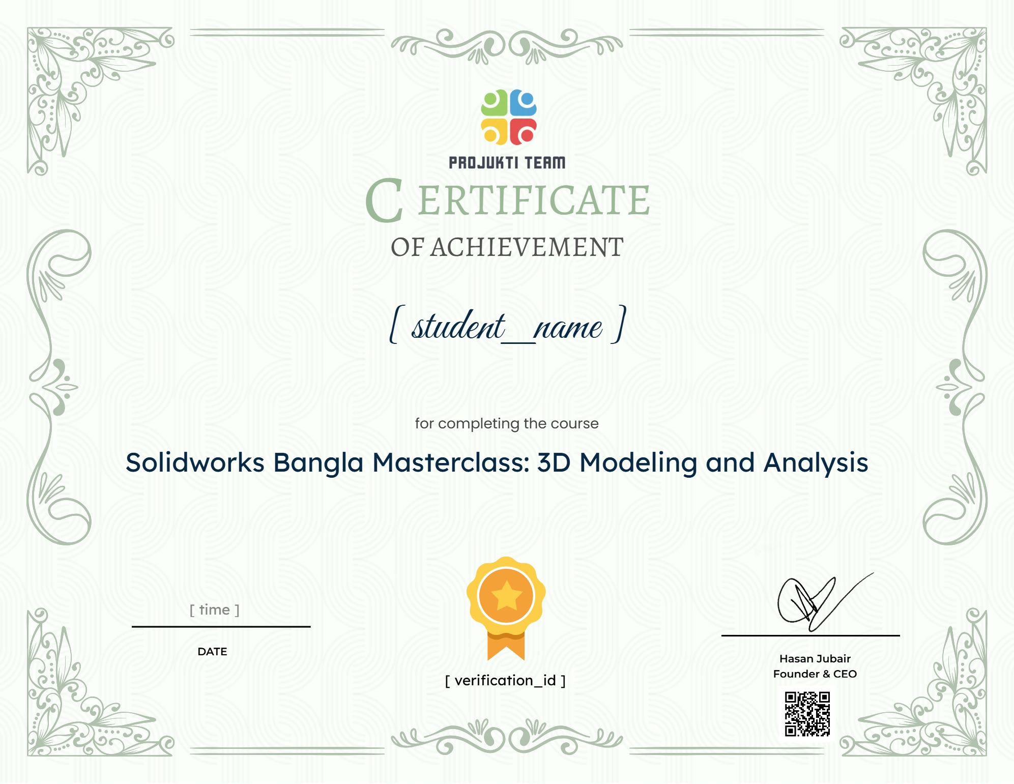
Earn a certificate
Add this certificate to your resume to demonstrate your skills & increase your chances of getting noticed.

Student Ratings & Reviews
যারা বাংলা ভাষায় কোর্স্ টি করতে চান তাদের জন্য চমৎকার একটি সুযোগ। ধন্যবাদ প্রযুক্তি টিম।


